Can you add the option of reviewing/looking into a chip once created? Especially useful for teaching purposes. If I missed out please point me how to do it. Thx and keep up the good work!
There needs to be workspace's in this game. One of the workspace will have almost unlimited space, unlimited available inputs and outputs. It will be the place where the Main Project or the Computer is going to be built. Upon Exit, the chips in the main workspace should remain and they should retain the data, location, etc. The second workspace should be for building the chips. It will be the same as the Workspace we currently have access to. I believe that this Feature, If Implemented can change the Game. We would finally be able to Build Computers, and Many many other things. It will open up almost infinite possibilities. Personally, I want to build a 4-Bit Computer (4-Bit Because of the Limitations). I know that I cannot build a Computer here due to the Limitations. Because the Parts such as Control Logic which is the most important part of the computer cannot be built as it requires ROM or RAM. and we cannot just make a ROM with data coded in upon placing it. and another important part is the Layout. I could just put all the Parts in one Chip but I want it all placed down separately and witness the Creation working. I can't do it due to limited space, Limited Input, outputs, etc.
The pixel index is can be changed using the Address Pins. The Address is represented in Binary. So, For example, If we want to change the pixel in the top left which is the first pixel we can leave all the address pins empty which sets the address/pixel index to 0 in binary.
After we select the Address of your Choice. We have to choose a color. Unfortunately, There is only 8 available Colors. There are 3 Color pins - Red, Green Blue. We can combine these colors to create another color such as pink, yellow, cyan etc. After we select the color of our choice, We can Update or Change the Pixel we chose to the color we selected by pulsing or bringing the Store Pin High. The store pin isn't edge triggered so can keep it high and actively change pixels.
It would be great if you could ask a chip to detect overlapping connections, which would automatically wire them together. Thanks for making this updated version of the game!
I have a problem with the clock and Key chips. If I hook the clock up to lamps, they will blink on and off every time the clocksignal enables nomatter if the signal of the clock is still on or not.T The only way to solve this issue that I found is to set the signal speed to slow.
Hello, There are some issues with Performance. I have built a 16 Byte RAM (Actully 8 Byte since it's 4-Bit). After I turned the RAM into a Chip, The project started taking way longer to load and the project lags when I grab it from the Chips in the Bottom. It lags because It's simulating 16 Registers and an Address Decoder. The 4-Bit Register had 4 1-Bit Registers Simulating inside it and the 4-Bit Address Decoder is simulating 16 4-Input AND Gate which is simulating 3 AND Gates. The 1-Bit Registers are Simulating 2 D Flip-Flops which is Simulating 1 D Latch which is Simulating 1 SR Latch and so on. You can see how performance expensive it is. I have a RTX 3080, Intel Core I7-10700 and 32 GBS of RAM so it isn't very hard for my computer to run but it will be very hard for a low-end computer. I think instead of Simulating basically an Entire Project, You could try instead use a different approach that will be more performance friendly. If this performance issue isn't fixed, then It might just become near impossible to make a entire computer or CPU in this Simulator because of very low performance. A single clock cycle might just take a few seconds or even a few minutes. It takes around 3 to 5 Clock Cycles to execute one Assembly Instruction. so, You can imagine how tedious it will be to run anything large.
Ok, I will. But, unfortunately I have exams till 16th June and I'm not able to use my PC so I will send it Later. Also you should make it so that the project saves what is in the main window where we build the circuits. And also the chips must retain their data. Same for the inputs and outputs too.
That is awesome. I love it. You know what would be even sweeter? If you could make it 2 digits on the segmented display, like to count up to 99. I don't know if it's possible with the space available on the board.
Hey. I'm pretty new to this simulator (Digital Logic Sim 2) and I have a project on Digital Logic Sim 1 that I would like to import on this version. Is it possible and, if yes, how do I do it ?
You need to find a folder where unity saves player prefs (You can surf the internet to discover how to find player prefs folder), then go to the folder Sebastian Lague->Digital Logic Sim-> Save Data, in save data choose your project and copy it. Return to the main(from where you go in Sebastian Lague) and get to Sebastian Lague _ Lime inc_->Digital Logic Sim->Save Data and paste your project
Go to save data and you will see project folders. Go to one of them and just copy it, go to another project folder, and paste it(but now we are working to import chips to another project only with one button).
Hello Bandera Cat! I have a lot of respect for your remix ! I just love this sim!
Thank for all the things you added for the DLS 2! But here's a list of things that would make it even better!
1- Ability to put multiple wires on a single output without ORing like a dumb. SERIOUSLY, PLEASE!! Would be EXTREMELY helpful!
2- Ability to copy and paste selection. Would be also so helpful
3- Ablity to put output or input on BOTH sides with an option to select if it's output/input
4- Ablity to put i/o's on the top and bottom, for more pins (please)
5- Add a 8x8 matrix LEDs screen so we can combine them and make graphics and the LED will stay ON the chip when created (that one will be incredible!!!!)
Hi ! I'm one of the contributors in this project. 1- It doesn't seem too complicated, i'll try to do that. 2-It would be cool, I will suggest it in the github repository. 3-Bandera Cat is working on it, or at least he was. 4-I think he is also doing that. 5-The LEDs screens has been added but it's a bit experimental. The LED don't stay on the created chip however, but it has been reported in the Github Repository's discussion.
It would be really cool to see you in the repository ! If you make suggestions in the "Discussions" tab, they would get much more visibility. I hope to see you there !
I'm loving this simulator right now, it's got the best feel of every logic circuit simulator I've found, and I have some suggestions for QOL stuff! It'd be really nice to be able to view the contents of created chips. For more expansive projects, a more readable way of organizing the chips would also be super cool. Thank you for updating this project and making it more usable for people learning basic computer principles!
Thank you so much for adding Longer Names and Delete Confirmation. You should add a way to Change the Width/Height of the Gates so it doesn't take up too much space and will be more efficent for making Large Chips such as BCD to Hex or Address Decoders.
So, okay. I can you explain how Address Decoder must work(I am not very good at it) and you said that you made RAM. Can you do a tutorial about how to do RAM or Address Decoder? (I often play this game and I want to make simply CPU)
Sure! I am also still learning these things. The video will be very messy since the space to make these modules is very limited and the max zoom out limit is too low and the HitBox issue when changing zoom level.
* Option to delete a project * Rename the chip SYMBOL DISP to be only SYMB. It is too big, taking space. * Option to start with only a NAND gate (instead of a NOT and an AND). You can create NOT and AND from a NAND. Good exercise for my students and more realistic considering what we see in the market for buying chips.
Hello. Thanks for the update on the linux version. I found a bug: the led output linked in a clock doesn't keep turned on during the whole time the clock is HIGH. The led just blinks quickly. It should stay ON while in HIGH, and OFF while in LOW. Thanks for looking into it.
I think I've found a bug, when I delete a gate that I used in another gate, it deletes both of them and it will show forever in that project the Inputs and Outputs that were in the gate, the only way to "remove" them is opening another project.
Hi, I would need to save a project in a way, that restores the main layer and all my created chips. If I load a saved project, only the created chips show up in the status line and not the wiring of the main layer. How can I save and represent all the work?
Can you add that when you are deleting a gate you first need to accept it or a button that allows you to return back in actions? it happened me today that i somehow deleted all of my gates in the project. Thank you :)
Mb you pressed debug mode. To know if you pressed debug or not in the top bar would be green buttons "Step" and "Clock", which means that you pressed debug mode. Just click again on it
I think it would be nice if there's a slider to change the clock speed and I don't know if this is a bug but if a Output is connected to a clock it turns on and off really quick like the output has a edge detector built in. If it's a feature then there should be a separate circuit for that.
Hello! I have a few Ideas for this Project. First, There really needs to be a way to Sort the Gates at the Bottom of the Screen. Second, Longer Gate Name Length, Third, A Larger Area to work with. Forth, A way to Edit the Created Logic gates so any mistake in a gate or circuit can be fixed.
Hey, I think this project is cool. I am experienced in the programming field and have many suggestions and I could even help you if needed. Is there any way I could DM you on some application such as discord?
← Return to game
Comments
Log in with itch.io to leave a comment.
Can you add the option of reviewing/looking into a chip once created? Especially useful for teaching purposes. If I missed out please point me how to do it. Thx and keep up the good work!
Yes, we want to add it
Hey. Does anyone know how to delay a signal using a chip ?
Also, in future updates, could you please add it as a default chip ?
Ok
Hello. Is it posible to import multiple chips at once ?
No
Ok thanks
You can go into the file location that has the chips and copy the chips into the folder you want to have them in
There needs to be workspace's in this game. One of the workspace will have almost unlimited space, unlimited available inputs and outputs. It will be the place where the Main Project or the Computer is going to be built. Upon Exit, the chips in the main workspace should remain and they should retain the data, location, etc. The second workspace should be for building the chips. It will be the same as the Workspace we currently have access to. I believe that this Feature, If Implemented can change the Game. We would finally be able to Build Computers, and Many many other things. It will open up almost infinite possibilities. Personally, I want to build a 4-Bit Computer (4-Bit Because of the Limitations). I know that I cannot build a Computer here due to the Limitations. Because the Parts such as Control Logic which is the most important part of the computer cannot be built as it requires ROM or RAM. and we cannot just make a ROM with data coded in upon placing it. and another important part is the Layout. I could just put all the Parts in one Chip but I want it all placed down separately and witness the Creation working. I can't do it due to limited space, Limited Input, outputs, etc.
This is a fantastic idea
Yes, I agree! And maybe an option to type in how many inputs, chips, or outputs you want to add too. This should be their next update.
Erm... How do the screen and key chips work ? 😂😅 Also, Project deletion is a bit buggy (Idk how to fix it...)
Which problems you have with Key chip?
Nothing is being output, and Idk how to make the key output something
Also idk if it is supposed to output something.
PS : the chip import is very buggy pls fix that for the next update, it's a very useful feature.
Yeah, we are fixing importer
You need to press key on keyboard
Thanks. And the screen ?
The Screen consists of 2 Main Components.
1. Pixel Index,
2. Color
The pixel index is can be changed using the Address Pins. The Address is represented in Binary. So, For example, If we want to change the pixel in the top left which is the first pixel we can leave all the address pins empty which sets the address/pixel index to 0 in binary.
After we select the Address of your Choice. We have to choose a color. Unfortunately, There is only 8 available Colors. There are 3 Color pins - Red, Green Blue. We can combine these colors to create another color such as pink, yellow, cyan etc. After we select the color of our choice, We can Update or Change the Pixel we chose to the color we selected by pulsing or bringing the Store Pin High. The store pin isn't edge triggered so can keep it high and actively change pixels.
It would be great if you could ask a chip to detect overlapping connections, which would automatically wire them together. Thanks for making this updated version of the game!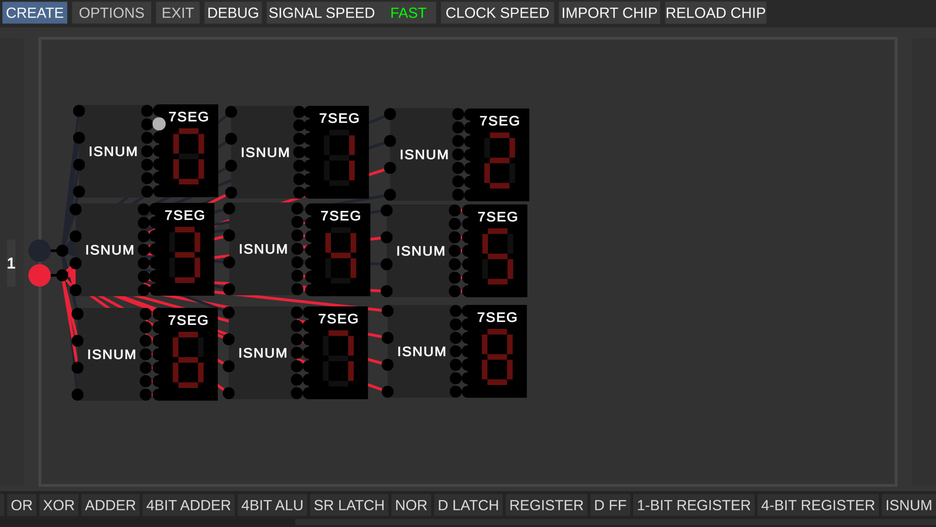
I agree. Thank you for making this version, I love it. It's so much fun !
I have a problem with the clock and Key chips. If I hook the clock up to lamps, they will blink on and off every time the clocksignal enables nomatter if the signal of the clock is still on or not.T The only way to solve this issue that I found is to set the signal speed to slow.
Cool
i was just trying to make something like this but with a lot more brute force by essentially multiplexing between a bunch of conditions.
The discord link is not working for me.
to me too
https://discord.gg/E5WtDC8y7T
I dont know how to rotate chips in version 1.2, can anyone help me?
Q and E
Thanks!
No, all projects are saved in another folder. If you download the new version all projects will be there
Hello, There are some issues with Performance. I have built a 16 Byte RAM (Actully 8 Byte since it's 4-Bit). After I turned the RAM into a Chip, The project started taking way longer to load and the project lags when I grab it from the Chips in the Bottom. It lags because It's simulating 16 Registers and an Address Decoder. The 4-Bit Register had 4 1-Bit Registers Simulating inside it and the 4-Bit Address Decoder is simulating 16 4-Input AND Gate which is simulating 3 AND Gates. The 1-Bit Registers are Simulating 2 D Flip-Flops which is Simulating 1 D Latch which is Simulating 1 SR Latch and so on. You can see how performance expensive it is. I have a RTX 3080, Intel Core I7-10700 and 32 GBS of RAM so it isn't very hard for my computer to run but it will be very hard for a low-end computer. I think instead of Simulating basically an Entire Project, You could try instead use a different approach that will be more performance friendly. If this performance issue isn't fixed, then It might just become near impossible to make a entire computer or CPU in this Simulator because of very low performance. A single clock cycle might just take a few seconds or even a few minutes. It takes around 3 to 5 Clock Cycles to execute one Assembly Instruction. so, You can imagine how tedious it will be to run anything large.
Can you send me project folder?
Ok, I will. But, unfortunately I have exams till 16th June and I'm not able to use my PC so I will send it Later. Also you should make it so that the project saves what is in the main window where we build the circuits. And also the chips must retain their data. Same for the inputs and outputs too.
ok
Thank you for your work, these are very nice additions
That is awesome. I love it. You know what would be even sweeter? If you could make it 2 digits on the segmented display, like to count up to 99. I don't know if it's possible with the space available on the board.
Also I love fiddling around with that 7SEG chip. 👍
Hey. I'm pretty new to this simulator (Digital Logic Sim 2) and I have a project on Digital Logic Sim 1 that I would like to import on this version. Is it possible and, if yes, how do I do it ?
You need to find a folder where unity saves player prefs (You can surf the internet to discover how to find player prefs folder), then go to the folder Sebastian Lague->Digital Logic Sim-> Save Data, in save data choose your project and copy it. Return to the main(from where you go in Sebastian Lague) and get to Sebastian Lague _ Lime inc_->Digital Logic Sim->Save Data and paste your project
Quick question. Is ALL game data stored in the place where I extracted the required files from the .zip folder ?
Mb
Thank you for your help. I found the Unity Player Prefs but it doesn't seem I can move them to another folder. Can you help with that
Go to save data and you will see project folders. Go to one of them and just copy it, go to another project folder, and paste it(but now we are working to import chips to another project only with one button).
Hello Bandera Cat! I have a lot of respect for your remix ! I just love this sim!
Thank for all the things you added for the DLS 2! But here's a list of things that would make it even better!
1- Ability to put multiple wires on a single output without ORing like a dumb. SERIOUSLY, PLEASE!! Would be EXTREMELY helpful!
2- Ability to copy and paste selection. Would be also so helpful
3- Ablity to put output or input on BOTH sides with an option to select if it's output/input
4- Ablity to put i/o's on the top and bottom, for more pins (please)
5- Add a 8x8 matrix LEDs screen so we can combine them and make graphics and the LED will stay ON the chip when created (that one will be incredible!!!!)
Thank you for all your work! - Gabriel
Hi !
I'm one of the contributors in this project.
1- It doesn't seem too complicated, i'll try to do that.
2-It would be cool, I will suggest it in the github repository.
3-Bandera Cat is working on it, or at least he was.
4-I think he is also doing that.
5-The LEDs screens has been added but it's a bit experimental. The LED don't stay on the created chip however, but it has been reported in the Github Repository's discussion.
It would be really cool to see you in the repository ! If you make suggestions in the "Discussions" tab, they would get much more visibility. I hope to see you there !
Having the ability to put multiple wires on a output would completely negate the reason to use a normal OR gate (I do agree its annoying)
how do you delete chips? i've tried for so long
Hover on chip in chip bar and press delete
thank you!
I'm loving this simulator right now, it's got the best feel of every logic circuit simulator I've found, and I have some suggestions for QOL stuff! It'd be really nice to be able to view the contents of created chips. For more expansive projects, a more readable way of organizing the chips would also be super cool. Thank you for updating this project and making it more usable for people learning basic computer principles!
how to zoom in / out
Ctrl + and Ctrl -
thanks
is it normal that when I create a gate with a clock, the clock in the gate doesn't work anymore?
Yes, It's normal
Thank you so much for adding Longer Names and Delete Confirmation. You should add a way to Change the Width/Height of the Gates so it doesn't take up too much space and will be more efficent for making Large Chips such as BCD to Hex or Address Decoders.
So, okay. I can you explain how Address Decoder must work(I am not very good at it) and you said that you made RAM. Can you do a tutorial about how to do RAM or Address Decoder? (I often play this game and I want to make simply CPU)
Sure! I am also still learning these things. The video will be very messy since the space to make these modules is very limited and the max zoom out limit is too low and the HitBox issue when changing zoom level.
So will you do video?
Three feature requests:
* Option to delete a project
* Rename the chip SYMBOL DISP to be only SYMB. It is too big, taking space.
* Option to start with only a NAND gate (instead of a NOT and an AND). You can create NOT and AND from a NAND. Good exercise for my students and more realistic considering what we see in the market for buying chips.
Hello. Thanks for the update on the linux version. I found a bug: the led output linked in a clock doesn't keep turned on during the whole time the clock is HIGH. The led just blinks quickly. It should stay ON while in HIGH, and OFF while in LOW. Thanks for looking into it.
І'am sorry. How can I fix it? Do I need to add a window with confirmation to delete?
Yes!
Also, This Software Lacks a Lot of things Such as copying a group of gates and pasting them and also the Hitbox issue with zooming.
New video on my channel
I think I've found a bug, when I delete a gate that I used in another gate, it deletes both of them and it will show forever in that project the Inputs and Outputs that were in the gate, the only way to "remove" them is opening another project.
Yeah I know this, I sometimes try to fix this bug, but nothing changes(
Where's the next update???
i created GLICHTED output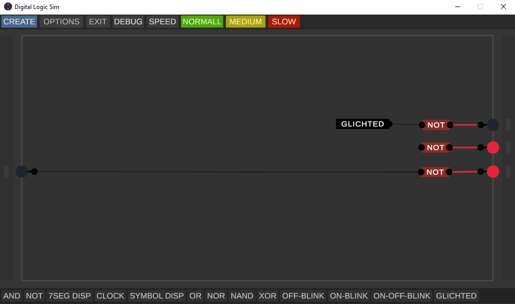
Wow, How u did that?
with two clocks and or
Hi, I would need to save a project in a way, that restores the main layer and all my created chips. If I load a saved project, only the created chips show up in the status line and not the wiring of the main layer. How can I save and represent all the work?
Can you add that when you are deleting a gate you first need to accept it or a button that allows you to return back in actions? it happened me today that i somehow deleted all of my gates in the project. Thank you :)
Ohh, okay I will add it
When's the next update. I would love to see increased or pretty much infinite Name Fields for Circuits and a way to Sort them differently.
An update will be on 17th
How can i zoom out?
Press Ctrl and - or Ctrl and +
I cant get the and or the not gates to output current, I'm doing it like in the video
Mb you pressed debug mode. To know if you pressed debug or not in the top bar would be green buttons "Step" and "Clock", which means that you pressed debug mode. Just click again on it
I think it would be nice if there's a slider to change the clock speed and I don't know if this is a bug but if a Output is connected to a clock it turns on and off really quick like the output has a edge detector built in. If it's a feature then there should be a separate circuit for that.
Ok, the Clock must work like that, it isn't a bug.
Hello! I have a few Ideas for this Project. First, There really needs to be a way to Sort the Gates at the Bottom of the Screen. Second, Longer Gate Name Length, Third, A Larger Area to work with. Forth, A way to Edit the Created Logic gates so any mistake in a gate or circuit can be fixed.
Good, thank you
There also should be Clocks so we don't have to Manually Pulse the Clock
Sorry, I have a new version. Now you can zoom and you have clock. I just forget to upload it. I will upload it up to 10min
Can you release a Windows version of this.
Yes. Now you can download windows version
Hey, I think this project is cool. I am experienced in the programming field and have many suggestions and I could even help you if needed. Is there any way I could DM you on some application such as discord?
Thanks, -BLOXBOT105
Yeah, Me Discord HECKER#4267
My username is MrSandMan, I added you and I need you to add me back.